Fun with solder
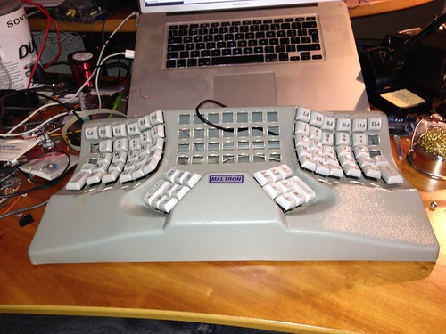
Where were we? Ah yes, I’d just unwired my Maltron, pulled out all the switches, ordered some Cherry MX brown stem keyswitches from a Deskthority Group buy and a Teensy++ from Pieter Floris. Now all I had to do was work out how I was going to wire the thing up. Jesse’s article had some great pointers, but as I disassembled the Maltron wiring loom, I gained a great deal of respect for their decision to use fine enamelled wire (which a bit of googling revealed to be solderable copper magnet winding wire - I bought some 30SWG stuff from wires.co.uk) which, because it’s thin and solid core is easy to bend into shape and, because the enamel coating melts into solder flux, is easy to solder without worrying about stripping insulation.
Where were we? Ah yes, I’d just unwired my Maltron, pulled out all the switches, ordered some Cherry MX brown stem keyswitches from a Deskthority Group buy and a Teensy++ from Pieter Floris. Now all I had to do was work out how I was going to wire the thing up. Jesse’s article had some great pointers, but as I disassembled the Maltron wiring loom, I gained a great deal of respect for their decision to use fine enamelled wire (which a bit of googling revealed to be solderable copper magnet winding wire - I bought some 30SWG stuff from wires.co.uk) which, because it’s thin and solid core is easy to bend into shape and, because the enamel coating melts into solder flux, is easy to solder without worrying about stripping insulation.
One thing that worried me about both Jesse and Maltron’s wiring was the fiddly nature of the way the wired the diodes in. The Maltron wiring only had diodes on a few keys, but I was looking to experiment with some serious remapping and possibly chording layouts - hardwiring a limited set of modifier keys wasn’t in my plan.
Diodes? Why diodes?
Before I talk about how I solved that problem, I’d best explain what the problem is. Consider the average computer keyboard with 105 or so keys. How do you work out which keys have been pressed without needing 105 I/O pins on your microcontroller? You arrange things in a matrix. We’ll worry about the physical layout of the board later, but here’s a schematic of a 5x5 key matrix which, with a bit of cunning, allows us to read which one of 25 keys is pressed with only 10 microcontroller pins

Suppose we apply a signal to the first column then, by looking at the pins attached to the rows, we can tell which switches in the selected column have been pressed by checking for the signal.

By cycling the symbol from column to column rapidly, we can scan the whole matrix.
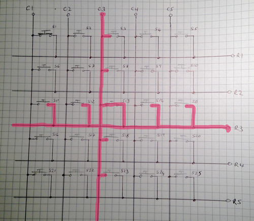
When two keys are pressed at the same time, we can spot them with this arrangement, but what happens when, say, three keys are pressed? Let’s press switches S1, S11 and S13 and find out. When we scan column one, all is well, we get the signal out on rows 1 and 3 as we expected, but when we scan column 3, which only has one key held down, we get a signal out on rows 1 and 3 as well. What’s going on?
Let’s trace the signal and see if we can work out how it gets to row one. The signal comes in on column 3, through S13 and onto row 3. But S11 is also on row 3, which means that the signal can flow through S11 onto column 1 and once it’s on column 1, it flows through S1, onto row 1 and confusion reigns.
Welcome to the wonderful world of ghosting.
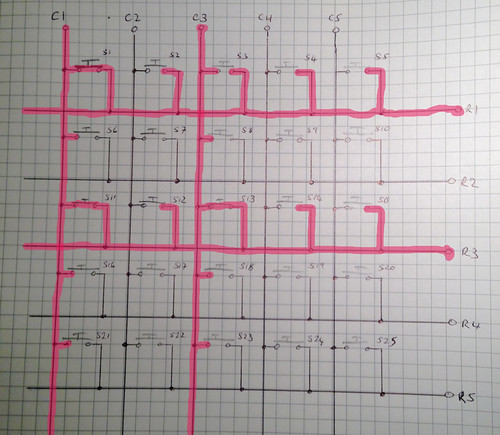
If you’re happy to live with only detecting when two keys are pressed simultaneously, you can correct for this in software by ignoring ambigous symbols (or by ignoring all signals which show more than two keys if you’re feeling lazy) and you can correct things for WASD gamers with some careful matrix layout to make sure that most of the common 3+ key combos aren’t ambiguous. Or you can spend a quid on a hundred 1N4148 diodes and invest some extra soldering time to wire things up like so:
« Signal: C3. Closed: C1R1, C1R3, C3R1. All Diodes »
With the diodes in place, the signal can’t go back through S1 and confuse things and your controller software can be much simpler.
The original Maltron wiring doesn’t put diodes on every key, just on all the modifier keys. Diodes may be cheap, but getting them wired into the matrix in the way Maltron did is a complete pain, doing it for over 100 keys was never going to be fun. But dammit, diodes on every key is just the Right Thing. There had to be a better way.
Diodes without (much) pain
If you’ve ever spent time soldering stuff, you’ll be aware that humans have a hard time soldering due to an acute shortage of hands. Generally you need to hold one component in one hand, another component in the other, the soldering iron in your other other hand and the solder wire in the… hmm… we appear to have run out of hands. Which is where things like vises come in handy. That way you can hold one component in the vise, lock the wire or component you’re trying to attach to it by twisting, wrapping or beinding things, leaving you with hands free for the iron and solder. Wiring diodes up to the keyswitches, which have to be installed in the keyboard case while you’re doing it, is the very definition of fiddly.
However, if you go and read things like the MX keyswitch’s datasheet, it makes reference to switches with diodes fitted and when you look at the bottom of a switch you’ll see a diode symbol and four small holes.
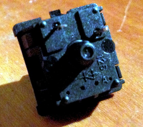
Time to crack a switch open

There’s quite a bit going on in there, but right where the four holes are is the interesting bit. We can bend the legs of a 1N4148 diode and feed ’em through the holes, pop the lid back on and it fits, clean as a whistle. We’re onto something here.
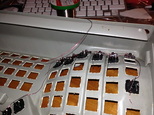
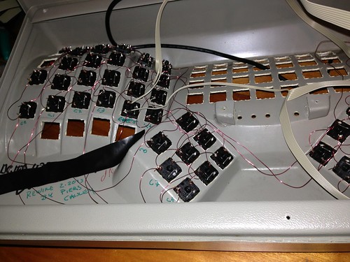
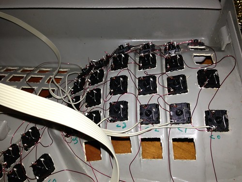
I’d decided to go with a reduced layout based on the ‘blue shift’ layout that Jesse cooked up so, although it was fiddly it didn’t take that long to pop another 59 keys and put diodes in there. After that, it was easy enough to wrap the anode lead around one of the switch’s pins, solder it in place and clip off the excess wire:
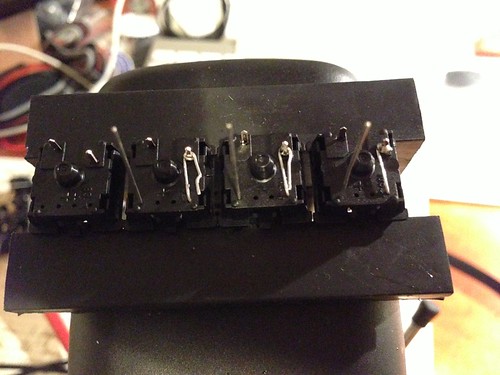
Now I had 60 keyswitches with diodes installed which I could pop into the keyboard case and wire up with magnet wire. I love solderable magnet wire. It’s magic stuff. Just wrap it tight round a pin, or the cathode lead of the diode and it stays in place while you solder it in place. I’m not going to pretend it was the work of moments, but it was pretty straightforward and I haven’t needed to resolder a single joint. There’s something very satisfying about watching capillary action suck molten solder into the joint. Physics is awesome.
Tune in next time to really learn about the importance of the pull-up resistor, how to roll your own (or someone else’s) keyboard firmware and some thoughts on where next.